3.3E Green Stormwater Infrastructure
Introduction
Green stormwater infrastructure (GSI) in transportation networks includes a range of stormwater management features such as bioretention, bioswales, and permeable pavement, which mimic natural hydrologic conditions. These features capture, infiltrate, and clean stormwater runoff, while maximizing benefits of green space in the transportation corridor.
GSI is a subset of greening. The broader term of greening can include many types of built features that provide greenspace, reduce stormwater runoff, and enhance ecological habitat. While urban landscaping provides some of these benefits by using street trees, grass, and other plantings, GSI provides these benefits through features that are specifically designed to:
Capture and manage stormwater runoff from tributary drainage areas,
Reduce the peak flow or volume of stormwater, and / or
Remove pollutants and sediment.
By incorporating GSI into the planning and design process, a project will be able to:
- Meet State, City, and, where applicable, watershed organizations’ stormwater management requirements.
- Reduce localized flooding for safer, more resilient, and greener neighborhoods.
- Reduce runoff volume and rate entering storm sewer and receiving waters.
- Calm traffic and beautify the urban landscape.
- Remove pollutants from stormwater runoff to protect the water quality of local lakes, wetlands, streams, and the Mississippi River.
- Increase green space and expand safe spaces for pedestrians and bicyclists.
- Extend the useful life of major capital street and sewer projects.
- Provide food and habitat for flora and fauna
GSI Design Criteria
Stormwater runoff enters a GSI facility either through constructed features such as a curb cut or roadway catch basin, or by flowing directly onto the facility from adjacent surfaces such as streets, sidewalks, parking lots, or planted areas. The water that enters the facility will either infiltrate into the ground, be absorbed by vegetation, or be filtered by soil or other media before it is directed to the storm sewer system.
Related chapters
- 3.3A Introduction and general guidance
- 3.3B Curbs
- 3.3C Greening
- 3.3D Street Trees
- 3.3F Utilities and signs
- 3.3G Street lighting
- 3.3H Bicycle and micro mobility parking
- 3.3I Driveways
- 3.3J Sidewalk cafes
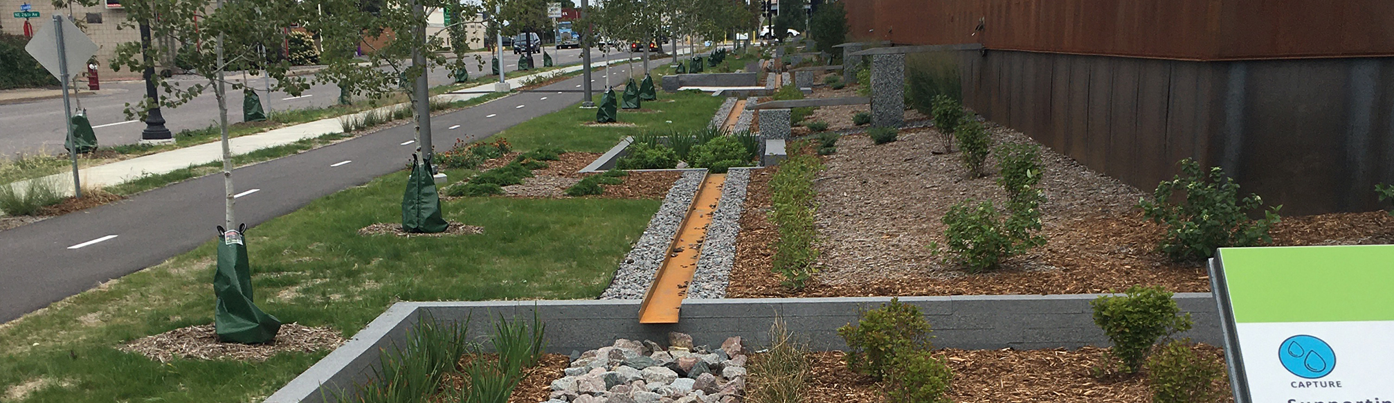
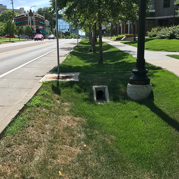
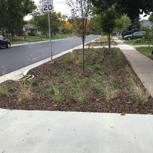
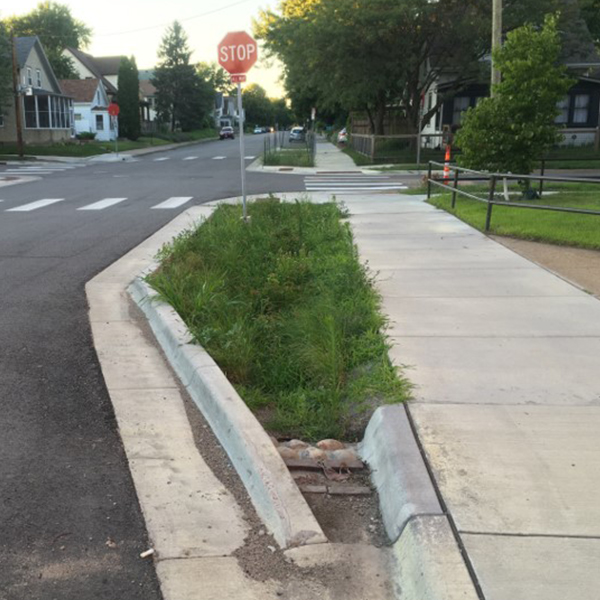
Examples of installed GSI in Minneapolis
Each GSI facility should be designed per local stormwater management requirements, which include:
GSI designs should generally comply with recommendations set forth in the following documents:
- Minnesota Stormwater Manual
- National Association of City Transportation Officials (NACTO) Urban Street Stormwater Guide
- City of Minneapolis Standard Specifications and Detail Plates
- City of Minneapolis Stormwater and Sanitary Guide or subsequent guidance and recommendations published by the Surface Water and Sewers Division for GSI and or drainage system work in the right of way
Figure 3.3E.1 summarizes the primary design criteria for GSI installations with applicable reference documentation and other notes. As the designer reviews the proposed project for potential GSI facilities, the drainage, hydrology, volume requirements, and setbacks of existing and proposed features will establish potential installation areas and types to meet performance requirements.
Figure 3.3E.1:
GSI Design Reference Criteria
|
Criteria |
Reference |
Notes |
|---|---|---|
|
Contributing Drainage Area |
Maximum drainage areas for type of GSI facility. |
|
|
Site Suitability |
Identify concerns such as steep slopes (>10%), hot spots, water quality needs or total maximum daily loads (TMDLs), prior to siting infiltrating GSI |
|
|
Hydrologic Parameters |
City of Minneapolis Stormwater and Sanitary Guide |
Parameter guidance (infiltration rates, runoff coefficients, methodology) and recommended modeling software |
|
Design Rainfall |
City of Minneapolis Stormwater and Sanitary Guide or Local Watershed District Permitting Requirement, whichever is stricter |
24-hour storm depths for standard return periods |
|
Soils and Infiltration |
Acceptable infiltration rate ranges for GSI and recommendations for secondary measures (see underdrains) |
|
|
Underdrains |
Minnesota Stormwater Manual |
Minimum pipe diameter, cleanouts, materials, spacing, and slopes |
|
Stormwater Volume |
Minnesota Stormwater Manual |
Water quality volume, channel protection volume, overbank flood protection volume, extreme flood control volume |
|
Pretreatment |
Minnesota Stormwater Manual |
Minimum sizing based on infiltration rate and GSI ability to treat percentage of the water quality volume |
|
Treatment |
Minnesota Stormwater Manual |
GSI facilities should be designed such that standing water drains or infiltrates through the system within 48 hours |
|
Horizontal Setbacks |
Minnesota Stormwater Manual |
Setbacks from water supply wells, buildings, property lines, streams, septic systems, slopes, and karsts |
|
Vertical Separation |
Greater than 3 feet from bottom of infiltration media to saturated soil or bedrock. Karst areas require special design. |
|
|
Utility Separation |
Minnesota Stormwater Manual |
Varies by case. The distance is generally 2 feet but needs to be reviewed with the utility type/owner and surrounding soil conditions. Some utilities such as telephone or water lines can be located within the facility. Others may require surrounding treatment or relocation to support or separate. Sanitary sewers or other utilities that could contaminate stormwater (or may be subject to infiltration and inflow risk) will need to be separate from GSI infiltration media. |
General Design Considerations
This section presents considerations to evaluate, select, and design GSI facilities. General GSI considerations are provided in the first part of this section and are followed by more detailed considerations for bioretention and permeable pavement facilities. Additional guidance and information can be found in the Minnesota Stormwater Manual and the National Association of City Transportation Officials Urban Street Stormwater Guide.
|
|
Maximize pervious surfaces as much as feasible |
|
|
Delineate and estimate the drainage areas impacted by and flowing into a street design project and consider multiple GSI tools or facilities to cumulatively manage stormwater runoff. |
|
|
3’ or wider buffers between the bike lane and traffic lanes are preferred. 2’ buffers can be used for very space-constrained environments provided the location is not adjacent to a parking lane and the bike lane and buffer area generally maintain a minimum combined width of 8’ (including the gutter). |
|
|
Design the GSI facility to provide water quality treatment for the required water quality volume. For each inflow point, define:
|
|
|
Consider soil amendments or an underdrain when the underlying soils’ infiltration rate is outside of the range presented in the City of Minneapolis Stormwater and Sanitary Sewer Guide. |
|
|
|
|
|
Consider the best practices when selecting and siting GSI throughout stages of planning and design so that GSI can provide multiple benefits. For example, bioretention should generally be favored over permeable pavement due to the additional benefits of increased green space and reduced hardcover. |
|
|
Coordinate with Surface Water and Sewers Design and Planning Group to identify flooding within and near the corridor and to determine if flood mitigation features can be incorporated into the project. |
|
|
Submit stormwater management plans with 30%, 60%, 90%, and 100% plans (see Documentation section). |
Bioretention
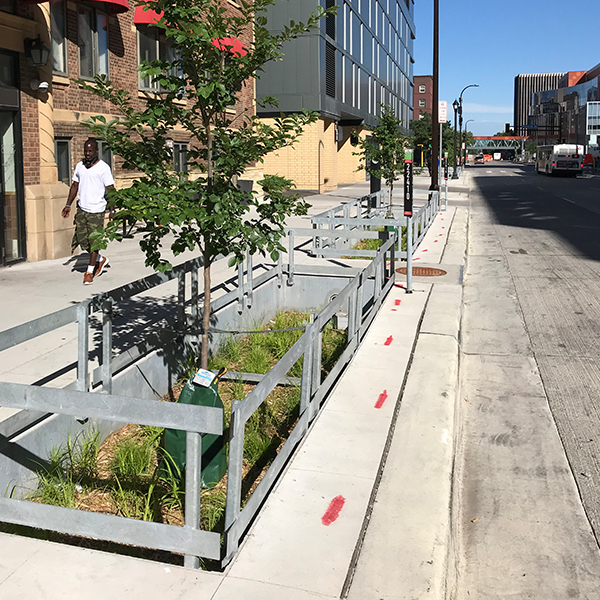
Bioretention includes small or mid-sized rain gardens, bioswales, tree trenches, and larger bioretention basins. These facilities are depressed, vegetated areas that capture, infiltrate or filter, and treat stormwater runoff. Bioretention may be installed as a vegetated, sloped facility such as a rain garden or bioswale or a vertical walled facility such as a planter or tree trench. Within street and roadway design, they are typically located within a median, along a boulevard, or in curb bump-outs. Engineered media can be used to amend the soils in the practice and promote infiltration.
Bioretention cells with sloped sides are preferred in locations with a larger available footprint for installation. Bioretention cells with vertical walls are more suitable for more urbanized locations, or locations with limited available footprint. The cell can be designed to infiltrate water into underlying permeable soils or can be filtered through soil or other engineered media and collected by an underdrain system when infiltration is not possible. Plantings provided in the facility enhance water quality by soaking up additional water and pollutants, and can range from grasses, flowers, and pollinators to shrubs and trees.
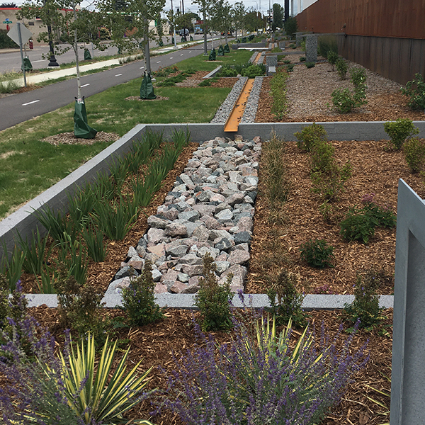
Figure 3.3E.2:
Sloped Surface Bioswale
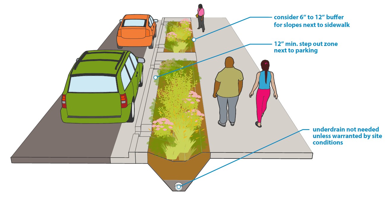
Figure 3.3E.3:
Vertical Wall Planter Bioswale
Bioswales are linear, sloped, vegetated areas designed to capture, treat, and convey stormwater runoff. Check dams can be used within the swales to reduce slopes, thereby encouraging detention, infiltration, and reducing flow velocities within the swale. Bioswales are a very flexible GSI facility that can be used in a variety of street improvement scenarios. Their linear shape can parallel road sections, follow medians, roadway swale/ditch segments, and linear green spaces adjacent to the curb and/or sidewalk.
A tree trench is a bioretention facility that includes a tree planted within engineered soil that is designed to store stormwater runoff and allow water to flow through the system and irrigate the tree. The media is a mixture of planting substrate and open graded aggregate that provides space to store runoff and for roots to grow. A tree trench can consist of one tree or can be a connected set of trees along a roadway. The system is designed to simultaneously treat stormwater runoff and promote healthy trees.
Bioretention design considerations
The following detailed design considerations should be considered when siting, selecting and designing bioretention GSI facilities:
FOOTPRINT:
- Design the engineered media mix thickness based on the site requirements. If the system design does not include infiltration, the media thickness should be between 2-6 feet (a minimum of 3 feet is recommended for plant health); see additional guidance on types of media mixes in Minnesota Stormwater Manual. Use of an underdrain may impact the media mix thickness.
- Impermeable liners and / or underdrains should be used in locations where infiltration is not recommended or possible due to site limitations.
- If the site has a limited footprint, structural cells or subgrade storage can occur beneath the pavement surface. Review the minimum soil volume requirement for plant health (volume based on plant selection).
- Structural cells should be used where risk of underground disturbance is minimal.
- Provide sufficient space for treatment of stormwater according to soil infiltration capacity.
- Pretreatment features should be included at the upstream end of the facility to improve pollutant and debris removal, to assist with long-term maintenance by protecting the function and stability of the treatment facility, and to prolong the life of the bioretention facility. Pre-treatment should be designed for the drainage area conditions and GSI facility.
CURB CUTS:
- Curb cuts directing runoff into a GSI facility should be lower than the gutter elevation to limit runoff bypassing the facility. This reduces blockages at the inlet and allows a shovel to be used to remove debris.
- Curb cuts directing runoff directly into a GSI facility should provide energy dissipation at the inlet.
- Curb cuts directing overflows out of a GSI facility should be located upstream of a catch basin to provide nearby connection to the sewer system. A downstream catch basin will allow overflow to enter the sewer system during a storm event that surpasses the GSI facility’s capacity.
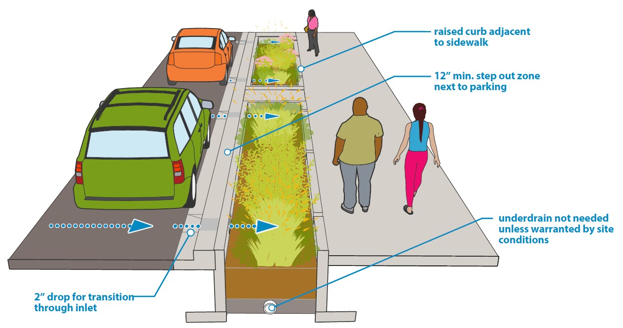
- A standard curb cut transition to forebay/pretreatment area provides a minimum 2-inch drop from the gutter to the top of the bay.
- Consider the uses of the curb space. Avoid sites near or adjacent to vehicle unloading/loading zones. A maximum continuous length of GSI adjacent to parking is 30 feet, at which point a minimum 5-foot-wide walkover should be provided. GSI facilities set adjacent to on-street parking should provide a level, 12-24-inch-wide step-out zone, depending on local parking conditions, along the curb to accommodate passenger entry and exit, and to reduce soil compaction and trampling.
- Bypass or overflow from larger storms can be achieved through: curb opening, grate structure, or inlet control.
- Preferred ponding depth is 6-18 inches. Greater ponding depths may be acceptable where pedestrian access is limited.
- Provide at least 2 inches of freeboard above the overflow elevation. Identify overflow location and shallowest freeboard on plans.
- The overflow opening may also act as in inlet if there is sufficient stormwater flowing to it. Review the need for pretreatment or stabilization for potential inflow through the overflow opening.
- If using catch basins to convey runoff to GSI facility, use standard catch basin design.
INFILTRATION:
- Infiltration is key for minimizing ponding (depth and duration) on the surface of the GSI facility. Where vertical space separations can be achieved and additional subsurface area exists, consider installing deeper gravel or stone bed layers or proprietary subsurface chamber systems for increased storage and infiltration.
- The depth and porosity of the gravel or stone bed below the engineered media is key for storing water and allowing water to slowly infiltrate into subsurface soils based on a measured or calculated rate of infiltration; consider a bypass or “chimney” of gravel or stone to convey water to gravel or stone bed more efficiently in installations that do not have underdrains.
- Low infiltration rates can be enhanced with engineered media to replace existing soils and/or vertical slots of gravel stone to create increased hydraulic connection to more permeable existing soils.
- If the underlying native soils do not meet minimum infiltration standards, an undrain can be used to provide additional drainage to meet drawdown requirements.
DIMENSIONS:
- A minimum width of 4 feet is required for a GSI facility.
- If vertical walls have greater than a 6-inch drop, use a vertical indicator, such as raised curbs. Railings or fencing can be used.
- Vertical indicators should allow for runoff to enter the bioretention area.
- Fence should be 18” to 36” in height and have no sharp edges.
- The fence must be open on street side (3-sided design).
- Fence should be 18” to 36” in height and have no sharp edges.
- Vertical indicators should allow for runoff to enter the bioretention area.
- Provide 6 to 12-inch shoulder next to sidewalks that don’t have vertical separation.
- If no shoulder is provided, the slope and sidewalk should be constructed to prevent undermining of the sidewalk.
- The shoulder should drop 1-2” and slope towards the ponding area at a slope of less than 5%
- Max slope is 3h:1v, unless next to existing tree, where max slope is 2h:1v.
- Install check dams the entire width of the bioswale, immediately following the swale stabilization.
- Provide at least 2 inches of freeboard above the design overflow and ponding depths.
- The longitudinal slope of the bioswale should not exceed 10%, the side slopes should be at a maximum 3h:1v and the bottom width should be at least 1-foot wide. Velocity should not exceed 4 fps (10-year, 24-hour storm). See Minnesota Stormwater Manual.
- GSI facilities should consider needs for features such as light bases, signposts, carriage walks, and utilities including placement of conduits and mid-block hand holes.
PLANTS:
- Use native vegetation/pollinators that are wet and dry tolerant and salt tolerant, refer to Minnesota Stormwater Manual
- Surfacing should be vegetation where:
- Boulevard is 2’ wide or wider (may be narrower where tapering
- Median is 4’ wide or wider, not including the curb space.
SOILS:
- See additional guidance on types of media mixes in Minnesota Stormwater Manual.
- Stabilize soils and provide plant protection using biodegradable geotextile. Any mulch within ponding areas must be secured in place by fabric.
- Mulch should be shredded hardwood and not dyed (non-colored); it should not be placed directly on tree trunks or shrub/plant stems but rather around in ring formation.
- Avoid compacting underlying soils during construction. Scarify soils towards the end of construction if compaction could occur on site.
- Develop phasing plan to prevent over-compaction, prevent erosion, and allow for plants to establish.
- Soils installed in GSI facilities should be lightly compacted to prevent settling that changes the elevation of the GSI facility surface. Do not use compaction equipment.
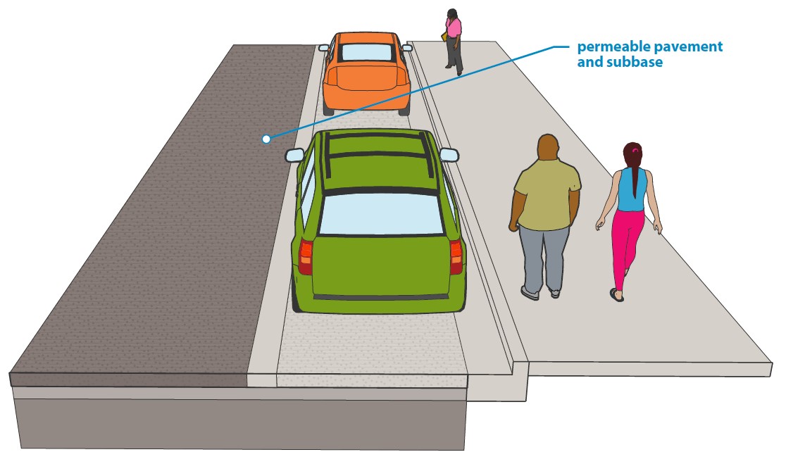
Permeable Pavement
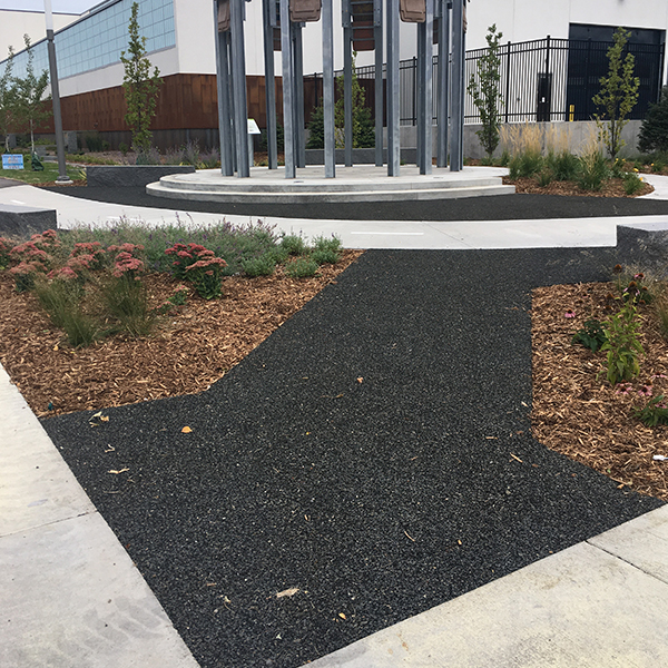
Permeable pavements are hard surfaces that allow water to flow through the surface and into a subbase of open graded rock. Pavements can consist of porous asphalt, pervious concrete, resin- bound aggregate, permeable interlocking concrete pavers, grass pave, flexible porous pavement, or alternative permeable surfaces. Beneath the pavement are layers of open graded rock that store water, remove pollutants, promote infiltration or retention of runoff. Permeable pavements can be used on the sidewalk, parking areas, driveways, roadways, and plaza spaces. This GSI type is best suited when space is limited, and they can serve as both a hard surface and a stormwater management practice. The base is designed to meet both the structural requirements of the pavement and any water volume and water quality goals.
Porous asphalt, pervious concrete, and other resin-bound aggregates should generally not be used in the right of way.
Permeable pavement spaces should not be sanded. Facilities should have small drainage areas and should be located where debris and sedimentation can be limited to prevent clogging of the openings. Ensure access to permeable pavement by sweeping equipment.
Permeable Pavement Design Considerations
In addition to the overall design considerations for GSI, permeable pavement can be designed for applicable street types where the following conditions occur:
- Avoid areas with frequent vehicle turning movements.
- Pavement uses:
- Low-volume, low-speed road
- Overflow parking or parking stalls
- Driveways or alleys
- Pedestrian areas
- Medians
- Furnishing zones
- Avoid road or pavement areas with frequent winter sanding.
- Avoid locations where spills may contaminate groundwater.
- Increased storage can be achieved beneath the system of pavers to increase infiltration capacity.
- Consider using permeable pavement up to the curb face to avoid water flowing down the gutter and bypassing the pavement.
- Review potential for sediment entrainment in the tributary storm water. Sediment deposition will increase the maintenance frequency.
- Ensure base course and bedding provide meet required pavement design.
Figure 3.3E.4:
Permeable pavements
Documentation
Provide documentation as noted in the Stormwater Management Plan Content Requirements in the Minneapolis Stormwater and Sanitary Sewer Guide. The documentation can be presented as a technical memorandum or a stormwater management report, based on the project requirements.
Layout Approval and 30% Design
In addition to the pre-construction components noted in the guide:
- Layout/approximate location and type of GSI facilities
- Drainage Areas to each GSI facility
- Required (if applicable) and provided water quality volume for entire project and per each GSI feature
- General detail for GSI facility: cross-section, inlet, bypass
- Pedestrian safety considerations (both how pedestrians will detect potential drop-offs and how GSI facilities can be used to increase safety)
- Connections to stormwater conveyance system
- Identification of increased water quality needs (including TMDL)
- Identification of GSI considerations, such as steep slopes (>10%), hotspots, soil conditions, anticipated utility conflicts, adjacent existing uses to remain
- Vegetation changes (such as tree removal and additions)
- Coordination needs/opportunities (adjacent properties)
- Identify maintenance responsibilities and funding sources
- Coordinate with Surface Water and Sewers Division on key aspects of project including sewer and drainage system condition assessment, flooding within corridor, and GSI siting and details
60% Design
- Design calculations that incorporate survey and geotechnical information
- Include annual pollutant removal for TP and TSS (from MIDS or other approved WQ model)
- Refined layouts with design details
- Landscape plan
- Utility conflicts and mitigation approach (move, remove, protect)
90% Design
- Incorporate comments from reviewers and revisions based on coordination done at 60%
- Same content as 60%.
Post Construction
- Delivery of As-built drawings of all infrastructure, contours, and soil modification.