Sidewalk-level protected bikeways are at or near the elevation of the sidewalk and are physically separated from the roadway by a vertical curb.
Introduction
Sidewalk-level protected bikeways are at or near the elevation of the sidewalk and are physically separated from the roadway by a vertical curb. Sidewalk-level protected bike lanes are the preferred bikeway type for any street reconstruction project on a street identified as a low stress bikeway on the All Ages and Abilities Network where a shared use path or neighborhood greenway are unfeasible or not preferred. They may also be implemented as part of a roadway retrofit project, but other forms of protected bike lanes are more common in that scenario due to retrofit cost realities.
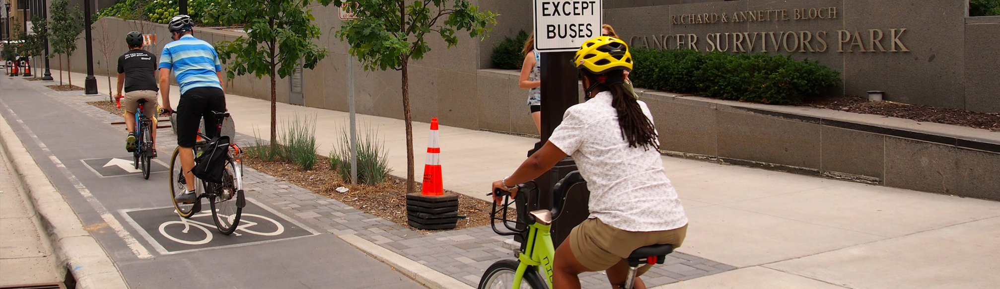
Sidewalk-level protected bike lanes on Washington Ave
Figure 3.4F.1:
Sidewalk-level protected bike lane dimensions table
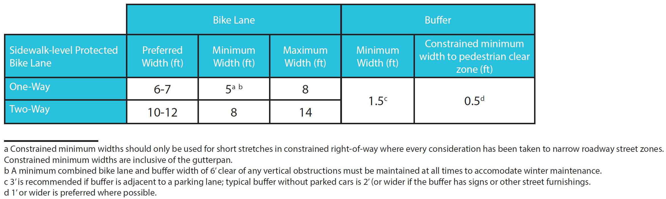
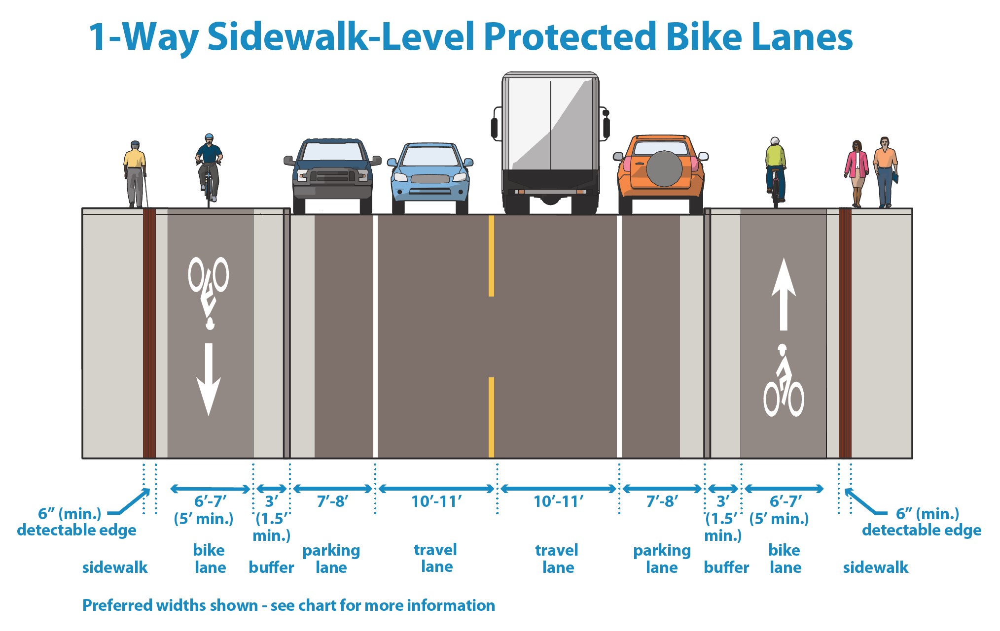
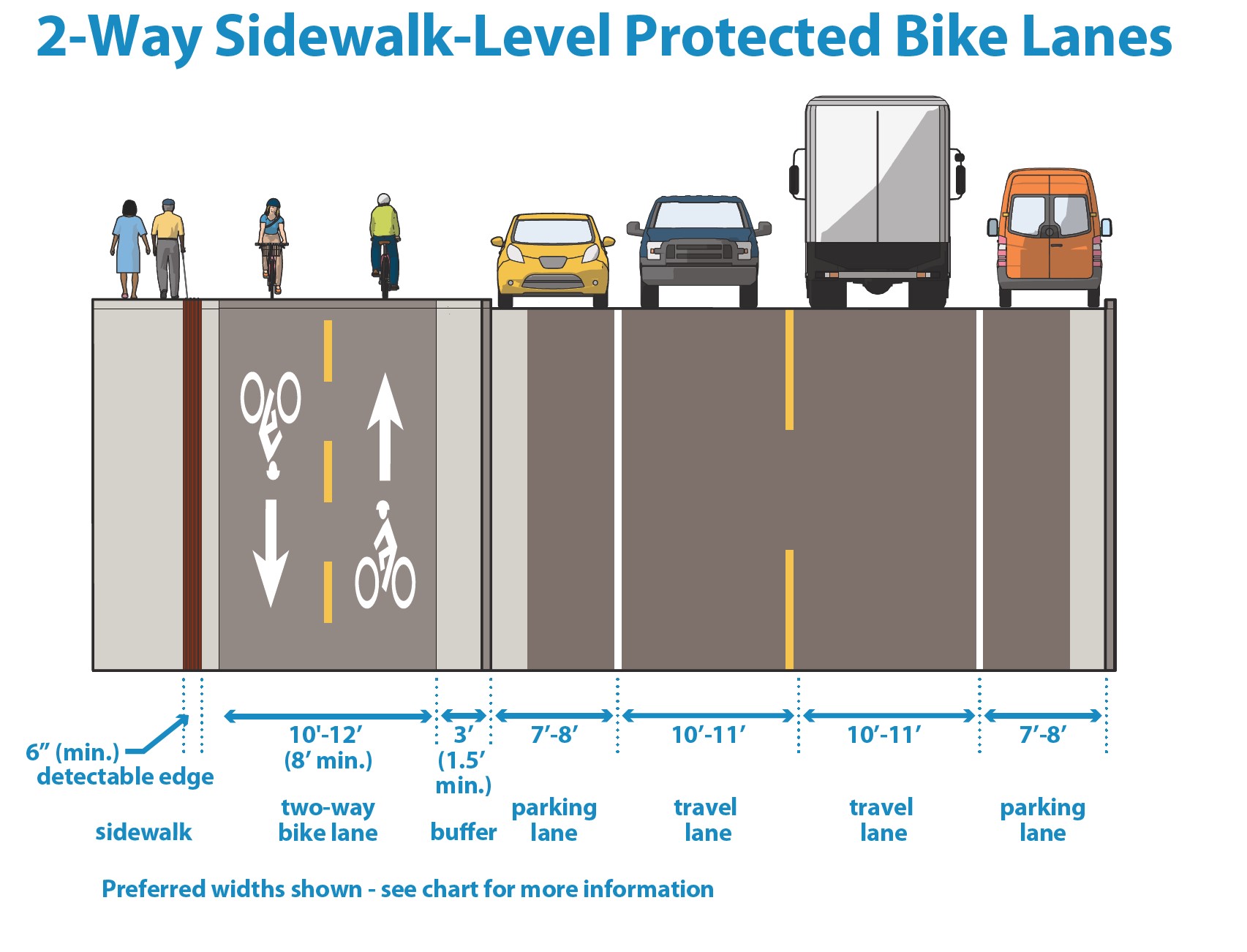
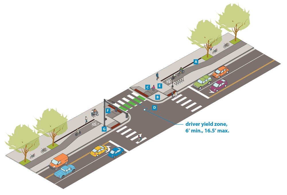
Figure 3.4F.2:
Sidewalk-level protected bike lane dimensions graphic
Design Considerations
|
Operation
|
May be designed for one-way or two-way bicycle traffic.
|
|
On-street to off-street transitions
|
On-street protected or un-protected bike lanes may transition to sidewalk-level protected bike lanes by employing bicycle-specific slip ramps. For slip ramp transitions, a pedal-compatible adjacent curb height (2” or less) or a mountable curb should be pursued between the bikeway and sidewalk/furnishing zone.
|
|
Maintenance
|
A constrained minimum bikeway + buffer width of 6’ is required to accommodate snow clearance/removal.
|
|
Greening
|
Buffer areas between the bike lane and roadway or sidewalk may be considered for greening where adequate space exists.
|
|
Buffer zones
|
Sidewalk-level protected bike lanes should have buffers between both the roadway and pedestrian clear zone.
- Buffers may be either hardscaped or landscaped depending on available widths and adjacent land uses and curbside contexts.
- On streets with higher pedestrian demand (e.g. Downtown Core and Mixed Use Commercial Connector streets), it’s preferable to have wider buffer space between the pedestrian clear zone and the bikeway. On streets with relatively fewer potential conflicts between pedestrians and bicyclists, it’s preferable to have wider buffer space between the roadway and bikeway.
- Wider buffers are also preferred outside of downtown to allow for additional snow storage space between the bikeway and curb.
- Sign posts, lighting, utilities, plantings, and street furniture may be located in the buffer areas.
- 2' Minimum clearance generally should be maintained from fixed objects to the bikeway operating area.
- 1’ minimum clearance can be considered for contiguous installations like fencing or railings and for objects placed at bikeway stop locations.
- See utilities and signs guidance or street lighting guidance for more details.
|
|
Materials
|
- When adjacent to a concrete sidewalk, the bikeway should use materials such as asphalt or colored concrete to visually differentiate the bikeway operating area from the sidewalk and adjacent buffer zones.
- Care should be taken to ensure the bikeway maintains a smooth and rideable surface, including limiting utility access covers and handholes in the bikeway operating area, and saw-cutting concrete rather than tooling joints in the bikeway area. When locations for utility access or handholes cannot be accommodated outside of the bikeway operating area, utility covers, maintenance holes, and handholes should be flush with the bikeway surface.
|
|
Detectable edge
|
In areas where a sidewalk-level bike lane is located adjacent to the pedestrian clear zone, a detectable edge (also referred to as a directional guideway or tactile edge) should be utilized to provide visual and tactile delineation between the sidewalk and the bikeway.
- Location and width. The detectable edge should generally be 6" wide and should be located parallel to the bikeway on the edge of the pedestrian clear zone next to the bikeway.
- The detectable edge is considered part of the sidewalk, or pedestrian clear zone, but must not encroach into the required 4’ pedestrian clear zone to ensure ADA accessibility.
-
A minimum of 3” is required between the bikeway and detectable edge due to installation needs. 6” is preferred if space allows.
-
Detectable edges are still a relatively new design treatment that people are learning how to use. Design consistency in the use of the detectable edge across projects is important to ensure legibility and allow for increase familiarity.
- Detectable edge should only be used when bikeway directly adjacent to the pedestrian clear zone. The detectable edge should end if the bikeway bends away from the pedestrian clear zone, leaving a boulevard or furnishing zone 3’ or greater between the bikeway and sidewalk (as shown in Figure 3.4F.3 below)
Figure 3.4F.3: Example of transition from detectable edge to boulevard and furnishing zone
- The detectable edge should continue across driveways where the bikeway and the pedestrian clear zone are directly adjacent.
-
Corners. The detectable edge should run along the bikeway up to the corner bicycle and pedestrian mixing zone (see design consideration E in protected intersections guidance). The detectable edge should not run through the corner mixing zone to prevent impacts to sloping grades, detectable ramps, APS push button placement, and to reinforce that pedestrians maintain the right of way in this area. Figure 3.4F.4 shows an example with proper use of detectable edge near a corner.
Figure 3.4F.4: Example of detectable edge at intersections (shown as black line)
-
Bus Stops. The detectable edge should break at dedicated crossing zones across the bikeway between the bus stop and the sidewalk, as shown in the image below. This signalizes that there is a corner or crossing zone for people who are using the detectable edge with a white cane.
Figure 3.4F.5: Example of detectable edge with breaks at bus stop access points
-
Material. Cast iron is the preferred material to be used for the detectable edge due to durability and winter maintenance needs. For areas where it is not possible to install cast iron detectable edge, the following materials may be considered:
-
Evaluation. The detectable edge was evaluated in 2021-2022 and the guidance below has been updated to reflect best practices for where and how to use this treatment. The full evaluation report can be found here.
|
|
Parking lane considerations
|
When locating a sidewalk-level protected bike lane adjacent to a parking or loading zone, a minimum buffer of 3’ should be maintained between the back-of-curb and the bikeway to accommodate door zone conflicts. In loading zones and areas with high parking turnover, consider paving the buffer area to accommodate access from the parking/loading zone to the sidewalk.
|
|
ADA considerations
|
Designers should implement strategies to support ADA access to parking spots, bus stops, and Metro Mobility drop off points along protected bike lanes. Additional details will be forthcoming in a future update to the Street Design Guide.
|
|
Intersection guidance
|
See also bikeway intersection design guidance.
|